Simulating Pure Pitching and Heaving Motions in OpenFOAM
Dynamic mesh techniques in Computational Fluid Dynamics (CFD) are pivotal for capturing fluid-structure interactions and other phenomena involving motion. In OpenFOAM, the prescribed motion method allows users to simulate complex scenarios using deformable meshes while maintaining computational efficiency. This article further explores the prescribed mesh motion technique, with a specific focus on simulating pure pitching and pure heaving motions. By the end of this guide, you’ll gain insights into implementing these motions in OpenFOAM and understanding their impact on flow dynamics.

Simulating dynamic motions such as pitching and heaving is critical in understanding the fluid-structure interactions that arise in various engineering and natural systems. Pure pitching and pure heaving motions, which involve rotational and vertical oscillations respectively, are widely studied in aerodynamics and hydrodynamics to analyze phenomena like lift generation, vortex dynamics, and energy harvesting. These simulations require precise control over mesh movement to accurately capture the interaction between the moving body and the surrounding fluid.
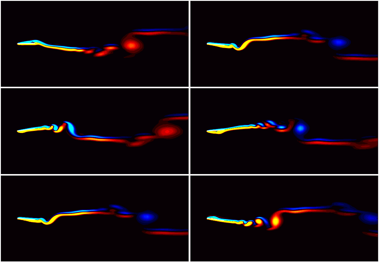
In my previous article, I introduced the concept of prescribed mesh motion in OpenFOAM, focusing on its application with deformable meshes. Building upon that foundation, this blog explores how to set up and simulate pure pitching and pure heaving motions using OpenFOAM’s dynamic mesh capabilities. I will cover the configuration of the motion profiles, mesh deformation techniques, and practical tips to ensure stable and accurate results. By the end of this blog, you’ll be equipped to implement these dynamic motions and analyze their impact on flow dynamics in your CFD simulations. As a tutorial case, I will select the flow around a thin-flat plate positioned parallel to the flow. To follow along, download the case setup from here.
Lets Begin!!!
Key Concepts of setting up prescribed motion
Prescribed motion is a dynamic mesh technique in OpenFOAM where the motion of a body or mesh is explicitly defined by the user, rather than being computed as a response to fluid-structure interactions. This approach is ideal for scenarios where the motion is known a priori, such as in studies of pure pitching or pure heaving motions. To enable dynamic mesh motion in OpenFOAM, several key settings must be configured to define how the mesh adapts to the prescribed motion. Specifically, four main changes need to be implemented:
- Add a
dynamicMeshDictfile in theCase/constant/directory. - Specify motion definitions in boundary conditions, using either the
pointDisplacementormotionUxfile. - Adjust boundary conditions in the velocity field to account for the movement of the cylinder.
- Include
cellDisplacementsettings in theCase/system/fvSolutionfile.
For a detailed explanation of these configurations, refer to my previous article.
In this blog, I will demonstrate how to set up pure pitching and pure heaving motions in OpenFOAM by incorporating these four changes into the simulation case. The motion profiles, which form the core of these setups, will be explicitly defined in the Case/0/pointDisplacement file.
Simulating Pure Heaving Motion
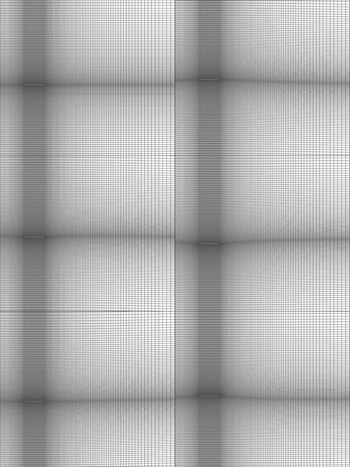
Pure heaving motion refers to the vertical oscillation of a body and is commonly used to analyze the behavior of wave energy converters, oscillating wings, or underwater vehicles. This motion is characterized by vertical displacement as a function of time, often described using sinusoidal or other periodic profiles. Before simulating pure heaving motion, ensure the geometry is symmetrical along the heaving axis to avoid unintended flow artifacts. Additionally, create a high-quality mesh with fine resolution near the moving body and in regions of interest, such as areas of expected flow separation or wake formation.
The motion profile is defined in the Case/0/pointDisplacement file. For the body (referred to as PRISM in my case), the pure heaving motion is prescribed using the oscillatingDisplacement boundary condition. This boundary condition implements a sinusoidal oscillation in the transverse (vertical) direction, represented mathematically as:
where, A is the amplitude, $\omega = 2\pi f$ is the angular frequency, and t is the time.
For this example, the amplitude (A) is set to 0.28, and the angular frequency (𝜔) is specified as 3.1415, corresponding to a frequency (𝑓) of 0.5. The motion is defined in the Case/0/pointDisplacement file as follows:
    PRISM
    {
		    type            oscillatingDisplacement;
        amplitude       ( 0 0.28 0 );
        omega           3.1415;
        value           uniform ( 0 0 0 );
    }
Once all other mesh motion setup requirements are fulfilled, use the moveDynamicMesh utility to simulate the pure heaving motion of the flat plate. To observe and visualize the motion, save your simulation data at regular time intervals.

In this blog, the focus is on simulating the mesh movement itself. Running the full simulation, including the application of boundary conditions and solving the flow field, is straightforward but requires some additional considerations. These aspects will be discussed in a future blog post.
Simulating Pure Pitching Motion
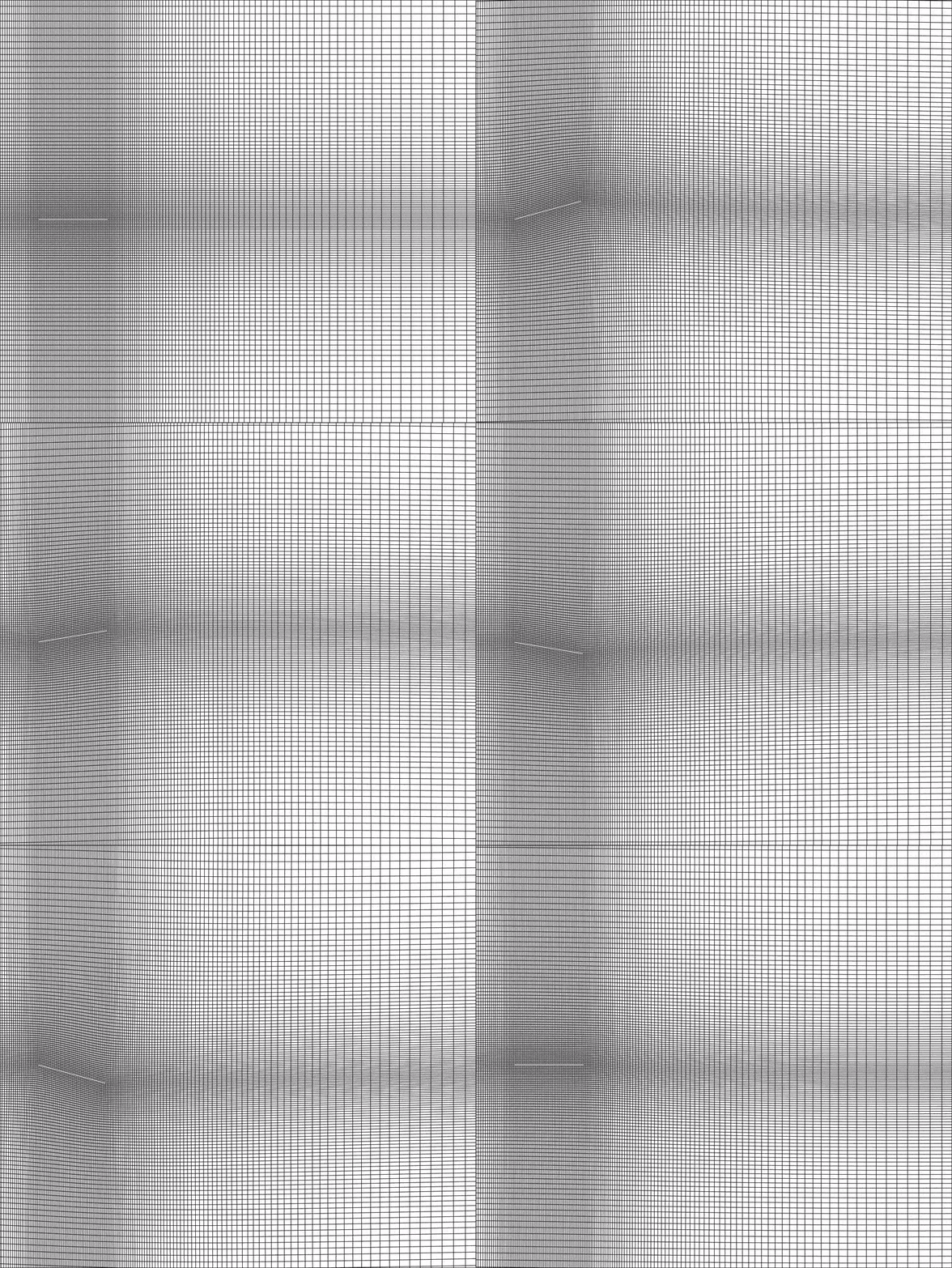
Pure pitching motion involves the rotational oscillation of a body about a fixed axis and is frequently used to study flow dynamics around airfoils, hydrofoils, or oscillating blades. To simulate this in OpenFOAM, the prescribed motion technique is employed to define the angular displacement as a function of time, typically using a sinusoidal profile. To ensure accurate simulation results, it is essential to align the pitching axis correctly relative to the mesh to avoid unintended distortions or flow anomalies, and use a high-quality mesh with sufficient refinement near areas of expected flow separation, vortex shedding, or other critical regions to capture detailed flow dynamics.
Unlike pure heaving motion, where displacement is prescribed, pure pitching motion requires defining the rotation angle. For this, OpenFOAM provides the angularOscillatingDisplacement boundary condition, which applies a sinusoidal variation to the angular displacement. The motion is mathematically described as:
where, A is the amplitude of pitching axis, $\theta_0$ is the initial angle of pitching, $\omega = 2\pi f$ is the angular frequency, and t is the time. I will keep these parameters same as above, and the boundary condition should be set as such,
For this case, the amplitude (A) is set to 0.28, the angular frequency (𝜔) is 3.1415 (corresponding to a frequency of 0.5), and the initial angle is 0. These parameters are defined in the Case/0/pointDisplacement file as follows:
    PRISM
    {
        type            angularOscillatingDisplacement;
        axis		(0 0 1);
        origin		(0 0 0);
     	  angle0		0;
        amplitude	0.28;
        omega		3.1415;
        value           uniform (0 0 0);
    }
Once the boundary condition and other mesh motion configurations are in place, use the moveDynamicMesh utility to simulate the pure pitching motion of the flat plate. To effectively visualize the motion, save your data at regular time intervals during the simulation.

Challenges and Best Practices
Challenges:
- Mesh Distortion: Dynamic mesh simulations involve continuous deformation of the computational mesh. Over time, excessive distortion can lead to poor cell quality, such as high skewness or non-orthogonality. This compromises the accuracy of the solution and may cause simulation divergence. For motions with large amplitudes or high frequencies, managing mesh quality becomes particularly challenging.
- Numerical Instabilities: Rapid or abrupt motions can lead to unsteady flow phenomena that challenge solver stability. High-frequency oscillations or sharp transitions in motion profiles may result in pressure-velocity coupling issues, leading to non-convergence of the solution.
- Boundary Condition Mismatches: Defining boundary conditions that align with the motion can be tricky. For example, inflow and outflow boundaries may not adapt well to rapid oscillations, resulting in unphysical reflections or instabilities near the boundaries.
- Computational Cost: Simulations involving dynamic meshes are inherently computationally expensive. Frequent mesh updates increase the computational overhead, especially for fine meshes or complex geometries. Ensuring stability might require smaller time steps, further increasing the cost.
- Motion Parameter Tuning: Improperly defined motion parameters (e.g., unrealistic amplitudes, frequencies, or directions) can lead to non-physical behavior, exaggerated mesh distortion, or missed physical phenomena.
Best Practices:
- Ensure High-Quality Mesh: Start with a well-refined mesh, particularly around regions of expected high gradients like the moving body’s boundary layer or wake region. Use tools like checkMesh in OpenFOAM to monitor quality metrics (e.g., skewness, aspect ratio) before and during the simulation. Consider using layered meshes near the moving body to reduce excessive cell deformation.
- Optimize Motion Parameters: Define motion profiles (e.g., sinusoidal pitching or heaving) based on realistic physical parameters like Reynolds number, amplitude, and frequency. Gradually increase the motion amplitude or frequency in a controlled manner if instabilities arise.
- Refine Time Steps and Solvers: Use a smaller time step (
deltaT) to handle high-frequency motions or rapid mesh deformation. Employ the Courant number (Co) as a guide to ensure numerical stability. Solvers like PIMPLE or PISO are well-suited for transient dynamic simulations. Adjust under-relaxation factors if needed. - Monitor Mesh Quality: Use OpenFOAM’s built-in mesh motion diagnostics to track mesh distortion during simulations. Enable options like mesh smoothing or layering in the
dynamicMeshDictto mitigate excessive deformation. - Use Appropriate Boundary Conditions: For oscillatory motions, ensure inflow and outflow boundaries can accommodate changes, such as by using wave-transmissive or zero-gradient conditions. Avoid fixed-value conditions that could conflict with the mesh motion.
Enjoy Reading This Article?
Here are some more articles you might like to read next: