Setting Up Overset Mesh Cases in OpenFOAM Made Easy
Published:
Overset mesh, also known as chimera or overlapping grid, is a powerful technique in CFD for handling complex geometries and moving bodies without remeshing. This capability in OpenFOAM simplifies simulations involving relative motion between components, such as propellers or rotor-stator interactions. In this article, I will explore the step-by-step process of setting up an overset mesh case in OpenFOAM, focusing on essential parameters, best practices, and potential pitfalls.
Overset mesh, often referred to as chimera mesh, is a groundbreaking approach in Computational Fluid Dynamics (CFD) for handling simulations involving complex geometries or relative motions between components. Unlike traditional meshing techniques, overset meshing enables overlapping grids, allowing seamless movement of components without the need for remeshing. In this blog, we build on the fundamentals and working principles discussed in my earlier article and dive into the practical aspects of setting up an overset mesh case in OpenFOAM.
To demonstrate the setup and capabilities of the overset mesh motion approach, I will use the example of an oscillating square cylinder with a prescribed frequency. This motion closely resembles the prescribed mesh motion case discussed in an earlier post. To follow along with this tutorial, you can download the case files from my GitHub repository here.
Lets begin!!!
Fundamentals of Overset mesh
Before we get into the details of the setup process, let’s quickly revisit the basics. Overset meshing involves the use of two or more grids: a background grid and one or more overlapping grids. These grids interact through interpolation, enabling seamless data transfer across grid boundaries. This approach is particularly effective for simulating scenarios involving moving bodies, such as oscillating cylinders, rotating machinery, or dynamic geometries. For a deeper dive into the theory behind overset meshing, feel free to refer to my earlier article.
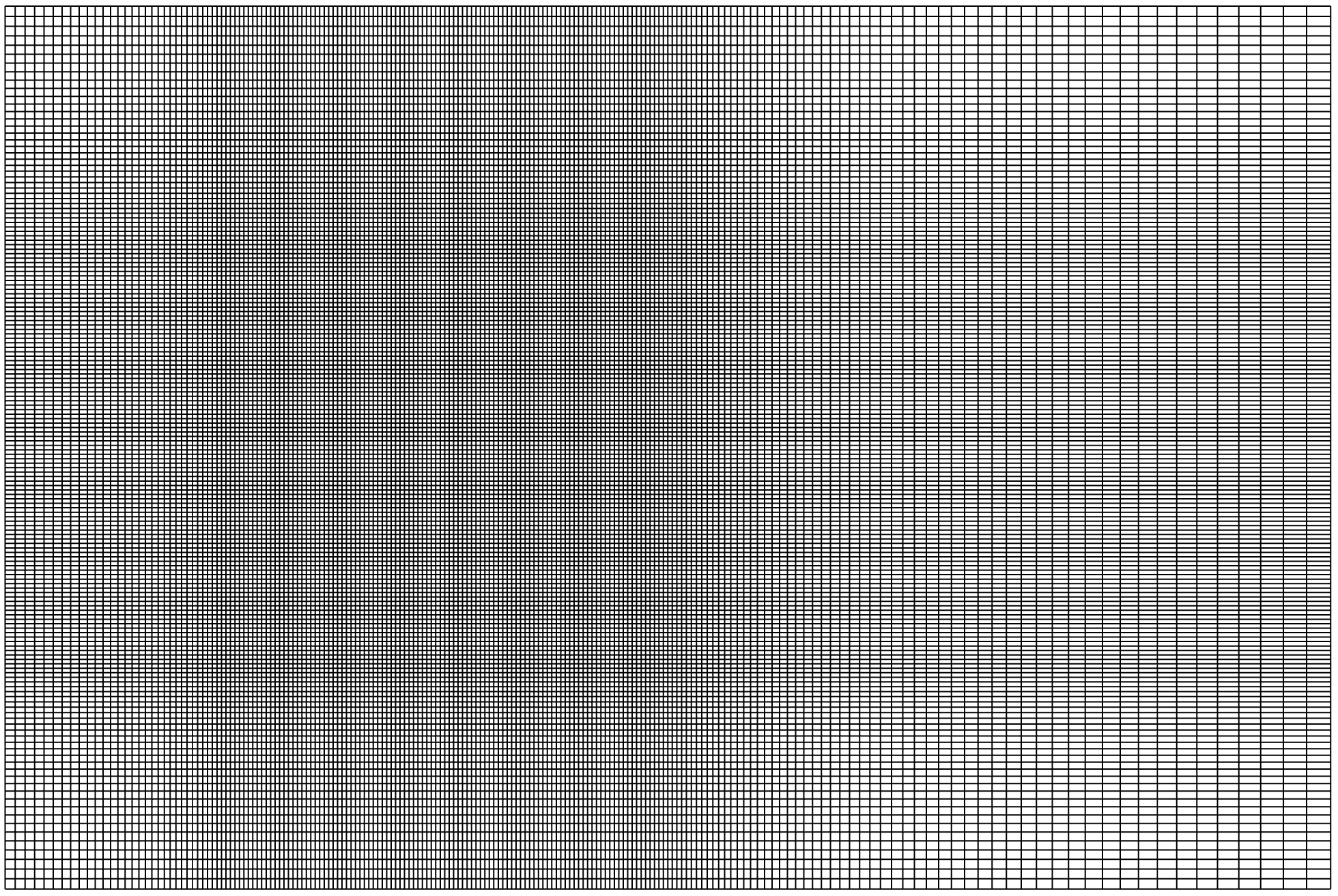
In this tutorial, we’ll work with one background grid and one overlapping grid. The background grid is a simple structured grid with localized refinement in the center, designed to accommodate the square cylinder and the overlapping grid. Here’s a visualization of the background grid:
The overset grid is a uniform grid centered around the square cylinder, and it looks like this:
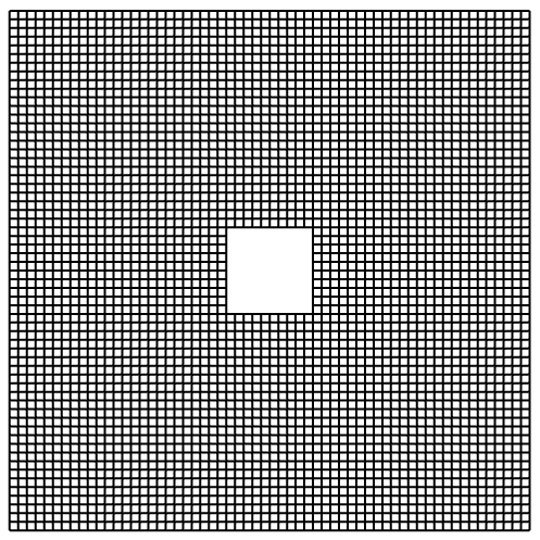
When designing the grids, the size of the background grid must ensure that the side and top boundaries have minimal impact on the wake development. Similarly, the overset grid should typically be a square or C-shaped domain with uniform spacing around the region of interest (in this case, the square cylinder). These considerations are critical for accurately capturing wake dynamics without interference from boundary effects.
If you’re unsure about your domain dimensions or wake behavior, consulting literature or research articles related to vortex dynamics and wake flows can provide helpful guidance. After all, references exist for a reason, right?
Case Setup
The first step in setting up an overset case is organizing the case directory. For an overset mesh simulation, the case directory should include two primary subfolders: background and overset. Organizing the case directory in this manner ensures a clean and modular workflow, making it easier to set up, modify, and debug overset simulations.
The contents of this folder should be as such:
OverSet_Base/
├── background
│   ├── 0
│   │   ├── U
│   │   ├── p
│   │   ├── pointDisplacement
│   │   └── zoneID.gz
│   ├── Background.msh
│   ├── constant
│   │   ├── dynamicMeshDict
│   │   ├── transportProperties
│   │   └── turbulenceProperties
│   └── system
│       ├── MultipleLines
│       ├── controlDict
│       ├── decomposeParDict
│       ├── fvSchemes
│       ├── fvSolution
│       ├── probes
│       ├── surfaces
│       ├── topoSetDict
└── overset
    ├── Square.msh
    ├── constant
    │   ├── dynamicMeshDict
    │   ├── transportProperties
    │   └── turbulenceProperties
    └── system
        ├── MultipleLines
        ├── controlDict
        ├── decomposeParDict
        ├── fvSchemes
        ├── fvSolution
        ├── probes
        └── surfaces
The background folder serves as the primary simulation directory, housing the background mesh and all simulation settings, including boundary conditions. This is where most of the case-specific configurations will be defined. In contrast, the overset folder should only contain the overset mesh file along with the constant and system subdirectories required for its setup.
To properly configure an overset mesh case in OpenFOAM, five main requirements must be addressed:
- Setup of the
<Case>/background/system/topoSetDictfile: This file defines the interpolation zones for overset meshing. - Configuration of the
<Case>/background/0/zoneIDboundary condition: Specifies the zone IDs to link the background and overset grids. - Definition of motion within the
<Case>/background/constant/dynamicMeshDictfile: Contains settings for mesh motion and dynamics. - Motion boundary conditions in the
<Case>/background/0/directory: Boundary conditions for the moving body or overset grid must be defined here. - Overset mesh solver settings: Configures the solver to handle overset interpolation and motion dynamics.
Each of these components is essential for ensuring the correct functionality of an overset mesh case. Let’s explore these setup requirements in detail, step by step.
Setting up of topoSetDict file
In the overset mesh approach, the simulation combines two meshes, the background and the overset mesh. To facilitate this integration, cell zones must be defined to distinguish between the two mesh regions. This is achieved using the topoSetDict file.
The topoSetDict file, located in <Case>/background/system/, should be configured as follows:
/*--------------------------------*- C++ -*----------------------------------*\
| =========                 |                                                 |
| \\      /  F ield         | OpenFOAM: The Open Source CFD Toolbox           |
|  \\    /   O peration     | Version:  v2412                                 |
|   \\  /    A nd           | Website:  www.openfoam.com                      |
|    \\/     M anipulation  |                                                 |
\*---------------------------------------------------------------------------*/
FoamFile
{
    version     1.0;
    format      ascii;
    class       dictionary;
    object      topoSetDict;
}
// * * * * * * * * * * * * * * * * * * * * * * * * * * * * * * * * * * * * * //
actions
(
    {
        name    OSGrid;
        type    cellSet;
        action  new;
        source  regionToCell;
        insidePoints ((0.15 0.15 0));
    }
    {
        name    BGGrid;
        type    cellSet;
        action  new;
        source  cellToCell;
        set     OSGrid;
    }
    {
        name    BGGrid;
        type    cellSet;
        action  invert;
    }
);
// ************************************************************************* //
Now, let’s break down what’s happening in the topoSetDict file:
- The first action defines a
cellSetnamedOSGrid, which identifies the region of cells within the overset zone. This essentially marks the cells belonging to the overlapping grid. - Next, another
cellSetnamedBGGridis defined, representing the background mesh region. - Finally, the
invertaction specifies that all cells not belonging to theOSGridare included in theBGGrid.
At this stage, two distinct cell sets OSGrid and BGGrid are established, laying the foundation for seamless interaction between the background and overset grids.
Setting up the zoneID
The zoneID is used to distinguish between the two cell sets defined earlier. This identification is critical for proper interpolation and data transfer between the grids. Using the setFields utility, we can assign unique IDs to the different cell sets.
To do this, you’ll need to configure the <Case>/background/system/setFieldsDict file as follows:
/*--------------------------------*- C++ -*----------------------------------*\
| =========                 |                                                 |
| \\      /  F ield         | OpenFOAM: The Open Source CFD Toolbox           |
|  \\    /   O peration     | Version:  v2412                                 |
|   \\  /    A nd           | Website:  www.openfoam.com                      |
|    \\/     M anipulation  |                                                 |
\*---------------------------------------------------------------------------*/
FoamFile
{
    version     1.0;
    format      ascii;
    class       dictionary;
    object      setFieldsDict;
}
// * * * * * * * * * * * * * * * * * * * * * * * * * * * * * * * * * * * * * //
defaultFieldValues
(
    volScalarFieldValue zoneID 123
);
regions
(
    cellToCell
    {
        set OSGrid;

        fieldValues
        (
            volScalarFieldValue zoneID 0
        );
    }

    cellToCell
    {
        set BGGrid;

        fieldValues
        (
            volScalarFieldValue zoneID 1
        );
    }
);
// ************************************************************************* //
This file specifies two distinct regions and assigns unique zoneIDs to the cells within each. Additionally, a zeroGradient boundary condition is applied to all boundaries, ensuring continuity between the zones.
Defining the motion
The next step involves defining the motion within the dynamicMeshDict file. This process closely resembles the setup for the prescribed mesh deformation case discussed earlier. In this instance, we will use the dynamicOversetFvMesh library to handle the overset mesh motion. To prescribe the motion, the multiSolidBodyMotionSolver is employed. The motion itself is defined based on the oscillatingLinearMotion properties, which include parameters for the amplitude and frequency of oscillation. For this case, we simulate the heaving motion of a square cylinder with the following properties:
- Amplitude: 0.05
- Angular frequency (𝜔): 6.28318
The <Case>/background/constant/dynamicMeshDict file is configured as follows:
/*--------------------------------*- C++ -*----------------------------------*\
| =========                 |                                                 |
| \\      /  F ield         | OpenFOAM: The Open Source CFD Toolbox           |
|  \\    /   O peration     | Version:  v2412                                 |
|   \\  /    A nd           | Website:  www.openfoam.com                      |
|    \\/     M anipulation  |                                                 |
\*---------------------------------------------------------------------------*/
FoamFile
{
	version     1.0;
    format      ascii;
    class       dictionary;
    object      dynamicMeshDict;
}
// * * * * * * * * * * * * * * * * * * * * * * * * * * * * * * * * * * * * * //

dynamicFvMesh       dynamicOversetFvMesh;

dynamicOversetFvMeshCoeffs
{
//    layerRelax 0.3;
}

solver          multiSolidBodyMotionSolver;

multiSolidBodyMotionSolverCoeffs
{
    movingZone
    {
        solidBodyMotionFunction oscillatingLinearMotion;
         amplitude       ( 0 0.05 0 );
        omega           6.28318;
        value           uniform ( 0 0 0 );
    }
}
// ************************************************************************* //
Once the motion is defined, the next step is to specify the region where this motion will be applied. While the cellSet containing the overset and background meshes has already been defined, we now need to create an additional region or zone for the moving body. To accomplish this, we use another topoSetDict file, named topoSetDict_movingZone, to define a cellZone within the BGGrid cell set. This zone will encapsulate the region where the prescribed motion will be applied. The new topoSetDict_movingZone file should be configured as follows:
/*--------------------------------*- C++ -*----------------------------------*\
| =========                 |                                                 |
| \\      /  F ield         | OpenFOAM: The Open Source CFD Toolbox           |
|  \\    /   O peration     | Version:  v2412                                 |
|   \\  /    A nd           | Website:  www.openfoam.com                      |
|    \\/     M anipulation  |                                                 |
\*---------------------------------------------------------------------------*/
FoamFile
{
	version     1.0;
    format      ascii;
    class       dictionary;
    object      topoSetDict;
}
// * * * * * * * * * * * * * * * * * * * * * * * * * * * * * * * * * * * * * //
actions
(
    {
        name    movingZone;
        type    cellZoneSet;
        action  new;
        source  setToCellZone;
        sourceInfo
        {
            set BGGrid;
        }
    }
);
// ************************************************************************* //
Setting up the overset boundary conditions
Next, we define the boundary conditions within the <Case>/0/ folder for the U, p, and pointDisplacement files. These conditions will include an additional boundary named OVERSET, which applies the overset boundary condition. This setup facilitates seamless information exchange between the background and overset meshes.
For the velocity field, the overset region will be specified with the overset boundary condition, and the square cylinder will have a movingWallVelocity condition as follows:
...
	  OVERSET
    {
        type                      overset;
    }

    PRISM
    {
        type                      movingWallVelocity;
		value                     uniform (0 0 0);
    }
For pressure, the overset region will again use the overset boundary condition, while the square cylinder will have a zeroGradient condition:
...
	  OVERSET
    {
        type            overset;
    }

    PRISM
    {
        type                      zeroGradient ;
    }
For the pointDisplacement file, the overset patch will use a zeroGradient condition, and the square cylinder will use a calculated condition:
...
	  OVERSET
    {
        patchType       overset;
        type            zeroGradient;
    }

    PRISM
    {
        type            calculated;
        value           uniform (0 0 0);
    }
Overset mesh solver settings
Finally, the solver settings for the simulation are defined in the <Case>/system/fvSchemes file. The configuration should look as follows:
ddtSchemes
{
    default         backward;
}

gradSchemes
{
    default         cellLimited Gauss linear 1;
}

divSchemes
{
    default         none;
    div(phi,U)      Gauss linearUpwind grad(U);
    div((nuEff*dev2(T(grad(U))))) Gauss linear;
}

laplacianSchemes
{
    default         Gauss linear limited 1;
}

interpolationSchemes
{
    default         linear;
}

snGradSchemes
{
    default         limited 1;
}

wallDist
{
    method          meshWave;
}

oversetInterpolation
{
    method              inverseDistance;
}

fluxRequired
{
    default         no;
    pcorr           ;
    p               ;
}
In this setup, particular emphasis is placed on defining the interpolation method. For this tutorial, the inverseDistance method has been selected to ensure accurate data transfer between the background and overset meshes.
Running the case
Running the overset case is not straight-forward as running any other case. This is because we specified couple of topoSetDict files and one setFieldsDict. As such, here are the steps to run the case:
Step 1: Mesh Generation
First, generate the meshes for both the background and overset grids by navigating into the corresponding directories and running the fluent3DMeshToFoam utility:
cd background/
fluent3DMeshToFoam Background.msh
cd ../overset/
fluent3DMeshToFoam Square.msh
cd ../background/
Step 2: Merging the Meshes
Since overset mesh operates on overlapping grids, the next step is to merge the two meshes. This is done using the mergeMeshes utility, and it should be executed from within the background directory:
mergeMeshes . ../overset/ -overwrite
After running this command, OpenFOAM will generate 8 patches, as indicated below:
patch names: 8(INLET OUTLET TOP BOTTOM SIDE1 SIDE2 PRISM OVERSET)
From this point forward, all operations will be conducted within the background directory.
Step 3: Defining Regions and Zone IDs
At this point, we have a merged mesh containing both the overset and background meshes. The next task is to define the different regions and zoneIDs as previously mentioned. To do this, run the following command:
topoSet
This will create the two cell sets. Next, define the zoneID. You will need to create a file called zoneID in the <Case>/0/ directory with the following content:
/*--------------------------------*- C++ -*----------------------------------*\
| =========                 |                                                 |
| \\      /  F ield         | OpenFOAM: The Open Source CFD Toolbox           |
|  \\    /   O peration     | Version:  v2412                                 |
|   \\  /    A nd           | Website:  www.openfoam.com                      |
|    \\/     M anipulation  |                                                 |
\*---------------------------------------------------------------------------*/
FoamFile
{
    version     1.0;
    format      ascii;
    class       volScalarField;
    object      zoneID;
}
// * * * * * * * * * * * * * * * * * * * * * * * * * * * * * * * * * * * * * //

dimensions      [0 0 0 0 0 0 0];

internalField   uniform 0;

boundaryField
{
    overset
    {
        type            overset;
        value           uniform 0;
    }

    ".*"
    {
        type            zeroGradient;
    }
}
// ************************************************************************* //
Run the following command to assign the zoneID:
setFields
This step is crucial as it ensures that the overset zones are properly defined.
Step 4: Defining the Moving Zone
Next, we define the moving zone. This can be done by running another topoSet command, but this time using the topoSetDict_movingZone file. To define the moving zone, use:
topoSet -dict system/topoSetDict_movingZone
Step 5: Solver Setup
At this point, we are almost ready to run the simulation. First, update the controlDict file to specify the writeInterval and endTime for your simulation, as shown below:
/*--------------------------------*- C++ -*----------------------------------*\
| =========                 |                                                 |
| \\      /  F ield         | OpenFOAM: The Open Source CFD Toolbox           |
|  \\    /   O peration     | Version:  v2412                                 |
|   \\  /    A nd           | Web:      www.OpenFOAM.com                      |
|    \\/     M anipulation  |                                                 |
\*---------------------------------------------------------------------------*/
FoamFile
{
    version     2.0;
    format      ascii;
    class       dictionary;
    object      controlDict;
}
// * * * * * * * * * * * * * * * * * * * * * * * * * * * * * * * * * * * * * //

libs
(
"petscFoam"
"overset"
"fvMotionSolvers"
);

application     overPimpleDyMFoam;//pimpleFoam;

startFrom       latestTime;//startTime;

startTime       0;

stopAt          endTime;

endTime         2; // 20 Through times

deltaT          0.005;

writeControl    timeStep;

writeInterval   10;

purgeWrite      0;

writeFormat     ascii;

writePrecision  8;

writeCompression on;

timeFormat      general;

timePrecision   8;

runTimeModifiable true;

// ************************************************************************* //
Finally, run the solver with the following command in your terminal:
overPimpleDyMFoam
Note: If you’re running a 2D case, ensure you specify empty patches for the side boundaries in <Case>/constant/polyMesh/boundary and <Case>/0/zoneID. Also, specify the overset boundary type for the overset patch in <Case>/constant/polyMesh/boundary.
To animate the mesh motion, you can use the moveDynamicMesh utility.